

A railway turnout is a key component of railway track infrastructure that enables trains to move from one track to another or pass through a track intersection. It serves as a track connection and crossing system, allowing trains to change direction while maintaining continuous railway operation.
Railway turnouts are an essential part of railway infrastructure. However, due to their complex structure, they are also one of the more vulnerable sections of a railway track and therefore require particular attention during maintenance and inspection.
The following sections outline the basic technical dimensional requirements for railway turnouts.
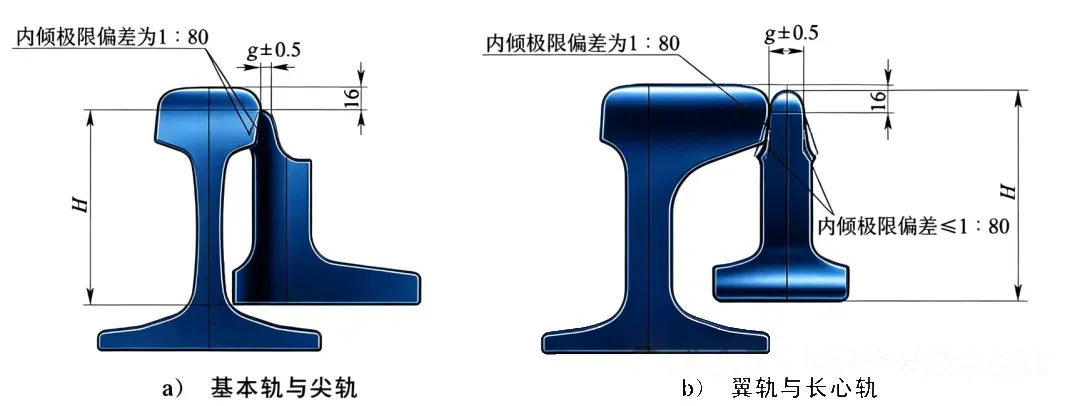
Figure 1 – Diagram of Rail Height, Rail Head Height, and Rail Inclination Deviation
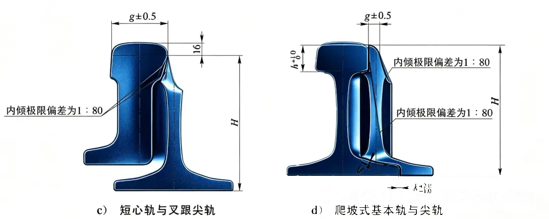
Figure 2 – Diagram of Rail Height, Rail Head Height, and Rail Inclination Deviation
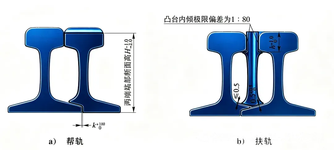
Figure 3 – Diagram of Check Rail and Guard Rail Position Deviations
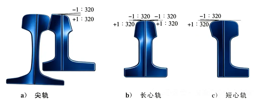
Figure 4 – Diagram of Rail Top Slope Deviations of Switch Rails and Frog Rails
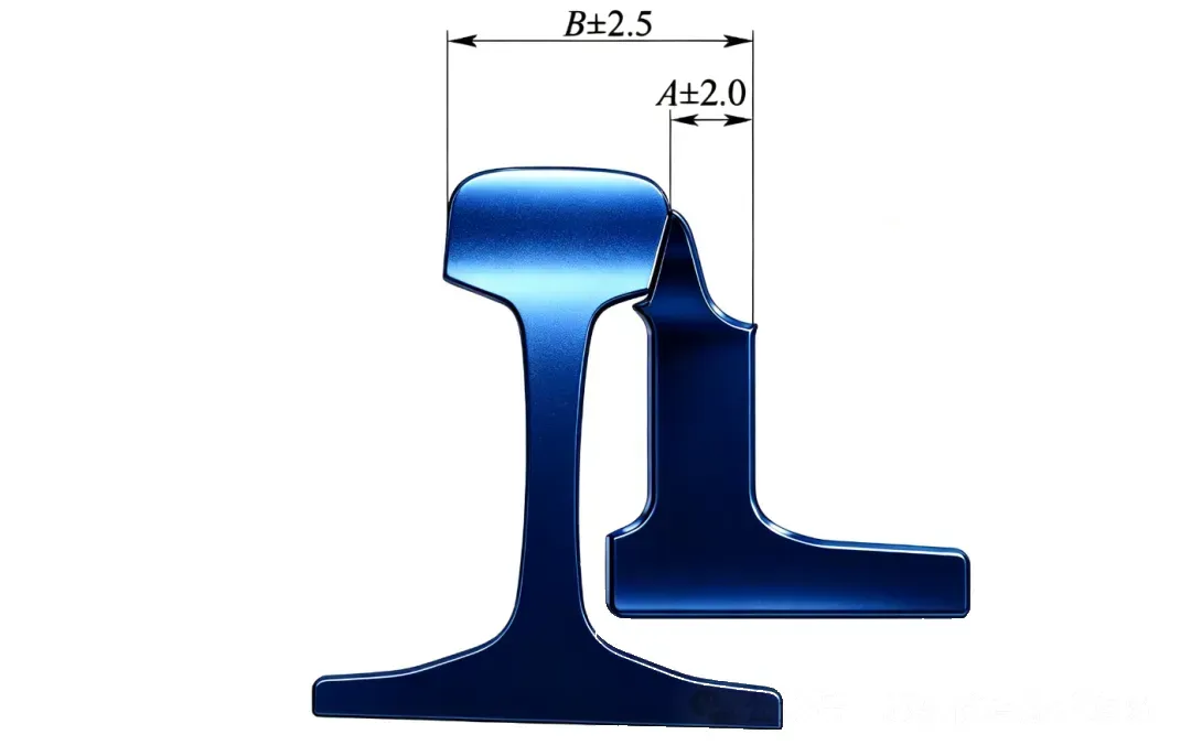
Figure 5 – Diagram of Dimensional Deviations Between the Inner Web of the Switch Rail and the Working and Non-Working Faces of the Stock Rail (AT)
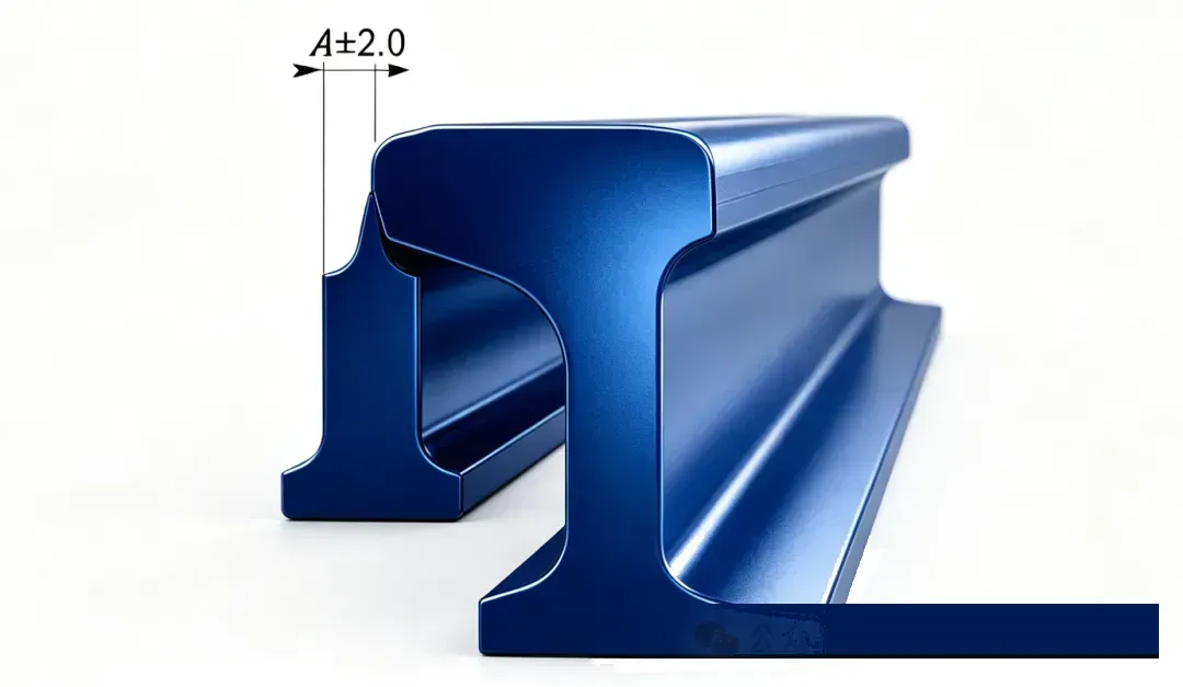
Figure 6 – Diagram of Dimensional Deviations Between the Inner Web of the Frog Point and the Working Face of the Wing Rail (AT)
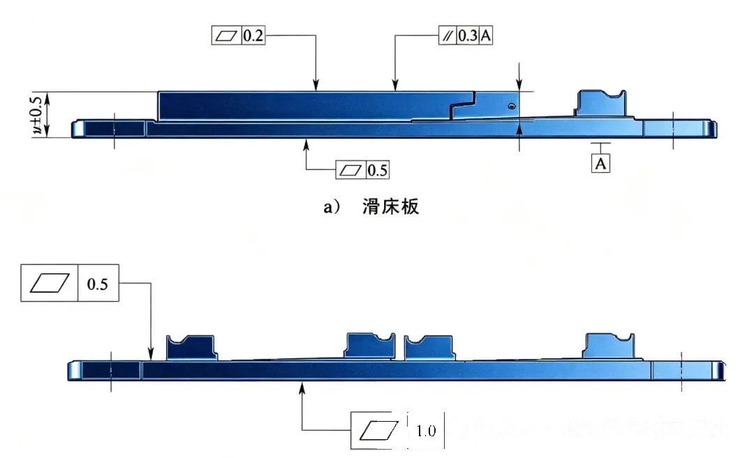
Figure 7 – Diagram of Flatness Deviations of Slide Baseplates and Supporting Plates
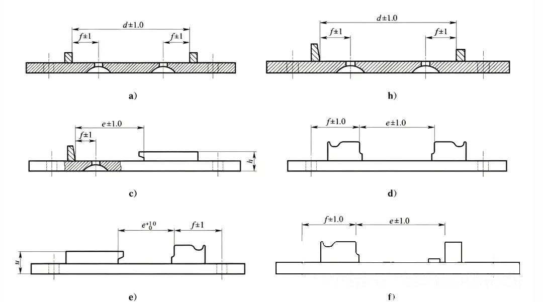
Figure 8 – Diagram of Dimensional Deviations of Baseplates
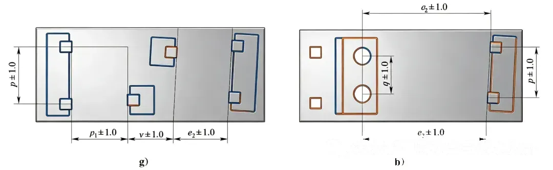
Figure 9 – Diagram of Dimensional Deviations of Baseplates
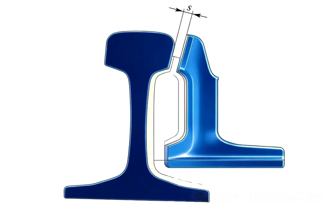
Figure 10 – Diagram of the Switch Rail and Stock Rail
When an external force is applied at the switch operating point, the gap between the switch rail and the stock rail within the rail head machining area shall meet the following requirements:
From the switch rail tip to the first operating point, the gap shall be less than 0.5 mm.
At all remaining positions, the gap shall be less than 1.0 mm.
This requirement is illustrated by dimension s in Figure 10.
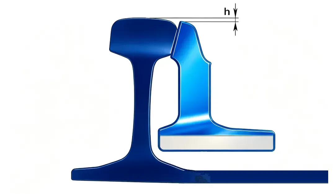
Figure 11 – Diagram of the Height Difference Between the Switch Rail and the Stock Rail
The allowable tolerance for the height difference (h) between the top surface of the switch rail and the top surface of the stock rail, measured at the 20 mm, 35 mm, and 50 mm cross-sections of the switch rail, shall be:
For turnouts with an allowable operating speed of 160 km/h less than V and V less than or equal to 200 km/h: ±0.5 mm.
For turnouts with an allowable operating speed of V less than or equal to 160 km/h: ±1.0 mm.
This requirement is illustrated by dimension h in Figure 11.
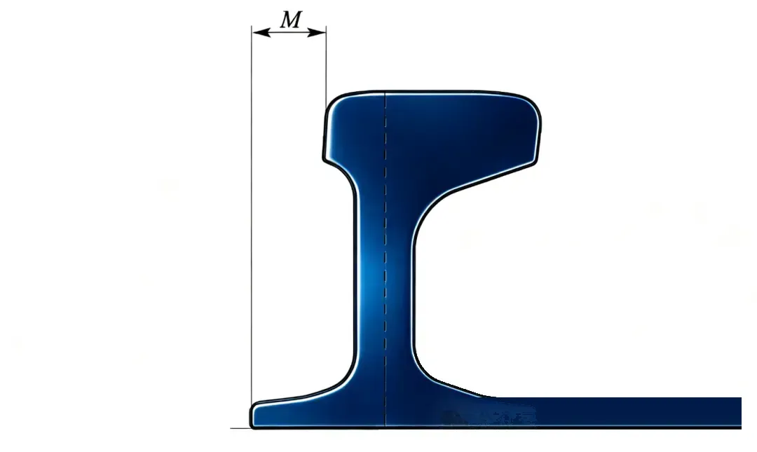
Figure 12 – Diagram of the Relative Distance Deviation Between the Outer Face of the Wing Rail Head and the Outer Face of the Rail Foot
At the operating point, the allowable tolerance for the relative distance (M) between the outer face of the wing rail head and the outer face of the rail foot shall be ±1.5 mm.
This requirement is illustrated by dimension M in Figure 12.
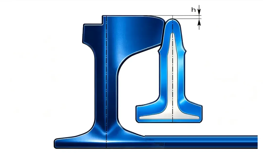
Figure 13 – Diagram of Height Difference Deviations Between the Frog Point and the Wing Rail at Different Inspection Cross-Sections
The allowable tolerance for the height difference (Z) between the top surface of the frog point and the top surface of the wing rail, measured at the 20 mm, 35 mm, and 50 mm cross-sections of the frog point, shall be:
For turnouts with an allowable operating speed of 160 km/h less than V and V less than or equal to 200 km/h: ±0.5 mm.
For turnouts with an allowable operating speed of V less than or equal to 160 km/h: ±1.0 mm.
This requirement is illustrated by dimension h in Figure 13.
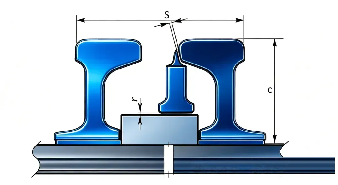
Figure 14 – Diagram of the Gap Between the Movable Frog Point and Slide Plate, and the Gap Between the Frog Point and Wing Rail
The bottom surface of the movable frog point shall be in contact with the slide plate. The gap requirements are as follows:
At both sides of the operating point, the gap shall be less than 0.5 mm.
At all remaining positions, the gap shall be less than 1.0 mm.
Gaps of 0.5 mm or greater shall not occur continuously.
These requirements are illustrated by dimension r in Figure 14.
When an external force is applied at the operating point or the locking hook is engaged, the movable frog point shall fit closely against both wing rails within the rail head machining area.
The gap requirements are:
From the frog point tip to the first operating point, the gap shall be less than 0.5 mm.
At all remaining positions, the gap shall be less than 1.0 mm.
These requirements are illustrated by dimension s in Figure 14.
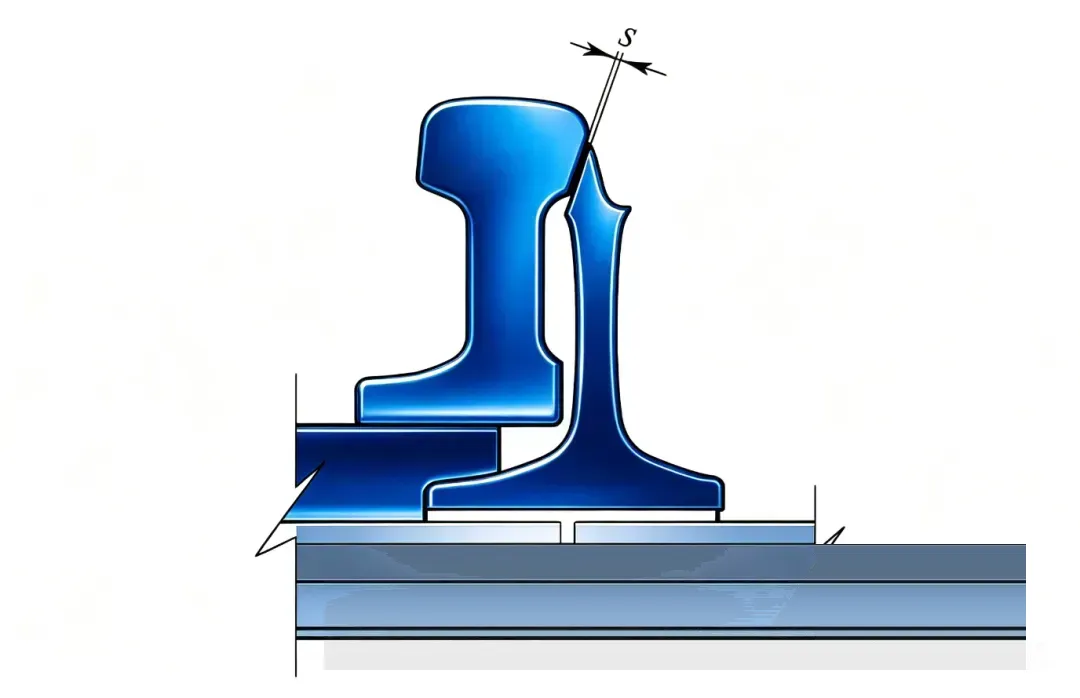
Figure 15 – Diagram of the Gap Between the Switch Rail at the Frog Heel and the Short Frog Point
When the turnout is aligned for the diverging route, the gap between the tip of the switch rail at the frog heel and the short frog point shall meet the following requirements:
Within 100 mm of the switch rail tip, the gap shall be less than 0.5 mm.
At all remaining positions, the gap shall be less than 1.0 mm.
This requirement is illustrated by dimension s in Figure 15.
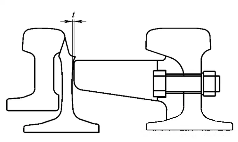
Figure 16 – Diagram of the Clearance Between the Top Iron and the Web of the Switch Rail at the Frog Heel
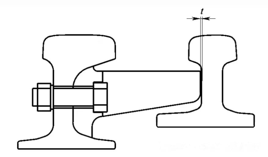
Figure 17 – Diagram of the Clearance Between the Top Iron and the Web of the Movable Frog Point
The clearance between the top iron (hold-down iron) and the web of the movable frog point or the switch rail at the frog heel shall be less than 1.0 mm, as illustrated in Figures 16 and 17.
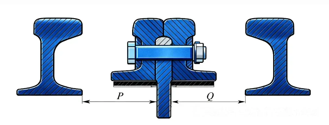
Figure 18 – Diagram of the Distance Between the Joint Iron and the Rail Foot of the Wing Rail
At the second operating point of the movable frog, the allowable tolerance for the distance between the joint iron connecting the long and short frog points and the rail feet of the two wing rails shall be ±3 mm.
This requirement is illustrated by dimensions P and Q in Figure 18.


